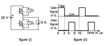
The chopper circuit shown in figure (i) feeds power to a $5 \text { A DC}$ constant current source. The switching frequency of the chopper is $100 ~\mathrm{kHz}.$ All the components can be assumed to be ideal. The gate signals of switches $S_{1} \text { and } S_{2}$ are shown in figure (ii). Average voltage across the $5 \text { A}$ current source is
- $10 \mathrm{~V}$
- $6 \mathrm{~V}$
- $12 \mathrm{~V}$
- $20 \mathrm{~V}$