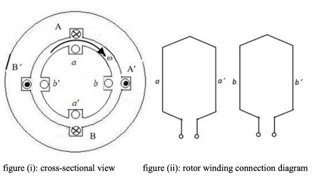
The four stator conductors $\left(\mathrm{A}, \mathrm{A}^{\prime}, \mathrm{B}\right.$ and $\left.\mathrm{B}^{\prime}\right)$ of a rotating machine are carrying $\mathrm{DC}$ currents of the same value, the directions of which are shown in the figure (i). The rotor coils $a-a$ ' and $b-b$ ' are formed by connecting the back ends of conductors ' $a$ ' and ' $a$ '' and ' $b$ ' and ' $b$ ', , respectively, as shown in figure (ii). The e.m.f. induced in coil $a-a^{\prime}$ and coil $b-b^{\prime}$ are denoted by $E_{a-a^{\prime}}$ and $E_{b-b^{\prime}}$, respectively. If the rotor is rotated at uniform angular speed $\omega \mathrm{rad} / \mathrm{s}$ in the clockwise direction then which of the following correctly describes the $E_{a-a^{\prime}}$ and $E_{b-b^{\prime}}$ ?
- $E_{a-a^{\prime}}$ and $E_{b-b^{\prime}}$ have finite magnitudes and are in the same phase
- $E_{a-a^{\prime}}$ and $E_{b-b^{\prime}}$ have finite magnitudes with $E_{b-b^{\prime}}$ leading $E_{a-a^{\prime}}$
- $E_{a-a^{\prime}}$ and $E_{b-b^{\prime}}$ have finite magnitudes with $E_{a-a^{\prime}}$ leading $E_{b-b^{\prime}}$
- $E_{a-a^{\prime}}=E_{b-b^{\prime}}=0$