A self commutating switch $SW$, operated at duty cycle $\delta$ is used to control the load voltage as shown in the figure
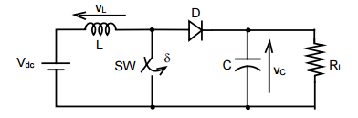
Under steady state operating conditions, the average voltage across the inductor and the capacitor respectively, are
- $V_{L}=0$ and $V_{c}=\dfrac{1}{1-\delta} V_{dc} \\$
- $V_{L}=\dfrac{\delta}{2}V_{dc}$ and $V_{c}=\dfrac{1}{1-\delta} V_{dc} \\$
- $V_{L}=0$ and $V_{c}=\dfrac{\delta}{1-\delta} V_{dc} \\$
- $V_{L}=\dfrac{\delta}{2}V_{dc}$ and $V_{c}=\dfrac{\delta}{1-\delta} V_{dc}$