The bus admittance matrix for a power system network is
$\begin{bmatrix}
-j39.9 & j20 & j20\\
j20 & -j39.9 & j20 \\
j20 & j20 & -j39.9
\end{bmatrix} pu.$
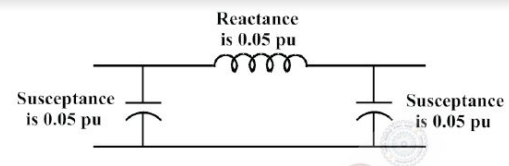
There is a transmission line, connected between buses $1$ and $3$, which is represented by the circuit shown in figure.
- $\begin{bmatrix}
-j19.9 & j20 & 0\\
j20 & -j39.9 & j20 \\
0 & j20 & -j19.9
\end{bmatrix} pu.$
- $\begin{bmatrix}
-j39.95 & j20 & 0\\
j20 & -j39.9 & j20 \\
0 & j20 & -j39.95
\end{bmatrix} pu.$
- $\begin{bmatrix}
-j19.95 & j20 & 0\\
j20 & -j39.9 & j20 \\
0 & j20 & -j19.95
\end{bmatrix} pu.$
- $\begin{bmatrix}
-j19.95 & j20 & j20\\
j20 & -j39.9 & j20 \\
j20 & j20 & -j19.95
\end{bmatrix} pu.$