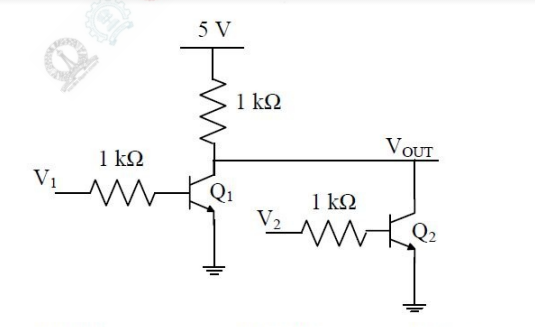
0 votes 0 votes The logical gate implemented using the circuit shown below where $V_{1}$ and $V_{2}$ are inputs (with $0$V as digital $0$ and $5$V as digital $1$) and $V_{out}$ is the output, is NOT NOR NAND XOR new gate2017-ee-1 + – Arjun asked Feb 26, 2017 • edited May 29, 2019 by Lakshman Bhaiya Arjun 15.9k points answer comment Share See all 0 reply Please log in or register to add a comment.