The Voltage Source Inverter $(VSI)$ shown in the figure below is switched to provide a $50 Hz$, square-wave ac output voltage $(vo)$ across an $R-L$ load. Reference polarity of $vo$ and reference direction of the output current $i_o$ are indicated in the figure. It is given that $R = 3\: \Omega$, $L = 9.55 \:mH$
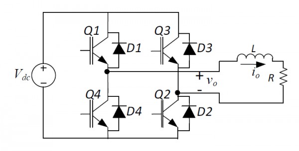
In the interval when $v_0< 0$ and $i_0> 0$ the pair of devices which conducts the load current is
- $Q1, Q2$
- $Q3, Q4$
- $D1, D2$
- $D3, D4$