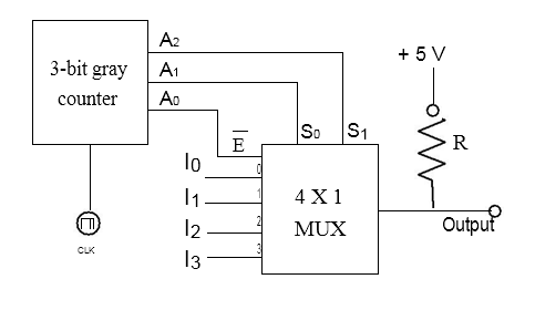
A $3$-$bit$ gray counter is used to control the output of the multiplexer as shown in the figure. The initial state of the counter is $0002$. The output is pulled $high$. The output of the circuit follows the sequence
- $I_0$, $1$, $1$, $I_1$, $I_3$, $1$, $1$, $I_2$
- $I_0$, $1$, $I_1$, $1$, $I_2$, $1$, $I_3$, $1$
- $1$, $I_0$, $1$, $I_1$, $I_2$, $1$, $I_3$,$1$
- $I_0$, $I_1$, $I_2$, $I_3$, $I_0$, $I_1$, $I_2$, $I_3$