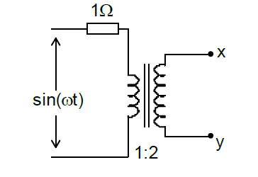
0 votes 0 votes Assuming an ideal transformer, the Thevenin’s equivalent voltage and impedance as seen from the terminals $x$ and $y$ for the circuit in figure are $2 \sin(wt) , 4 \Omega $ $1 \sin(wt), 1\Omega$ $1 \sin(wt), 2\Omega$ $1 \sin(wt), 0.5\Omega$ Electric Circuits gate2014-ee-2 thevinin-circuit ideal-transformer + – makhdoom ghaya asked Feb 11, 2017 • edited Sep 24, 2020 by go_editor makhdoom ghaya 9.4k points answer comment Share See all 0 reply Please log in or register to add a comment.